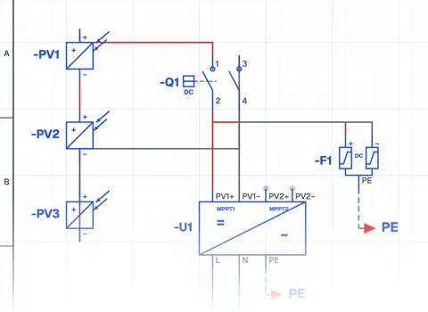
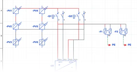
Control circuits.
The 62 circuits of the CoilPath library. What each one is for, part of its schematic and the parts used. Open it in the app and run it in the simulator.
Motor control circuits
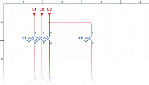 Contactor Connection
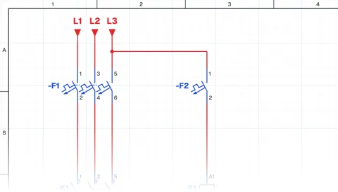 Contactor Connection with a Phase-Neutral Coil
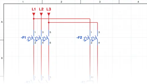 Contactor Connection with a Phase-to-Phase Coil
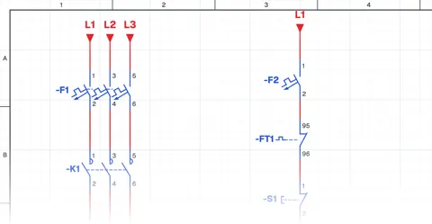 Direct-On-Line Starting Circuit for an Induction Motor
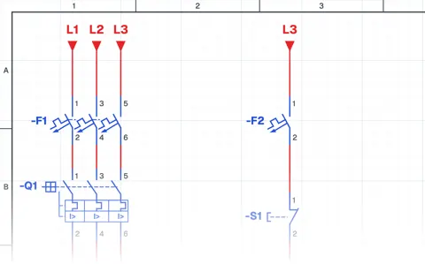 Induction Motor Jog (Inching) Circuit
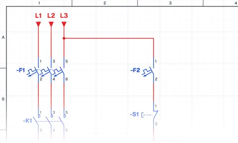 Seal-in Circuit (Continuous Running of an Induction Motor)
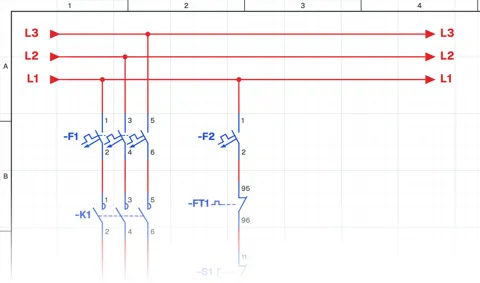 Seal-in Circuit (Continuous Running of an Induction Motor with a Relay)
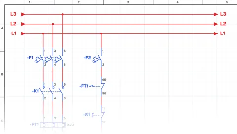 Jog Button with Momentary Running and Seal-in Cancel Circuit
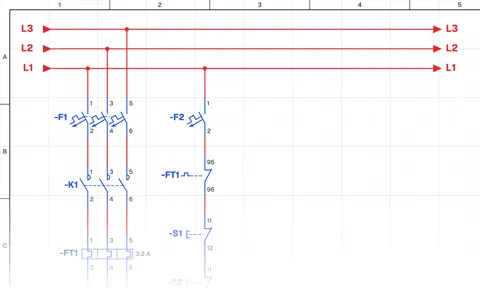 Seal-in Circuit with Start–Stop Control from Three Locations
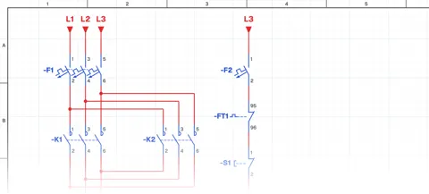 Forward–Reverse Direct-On-Line Starting Circuit
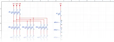 Sequential Induction Motor Starting with Timer Relays
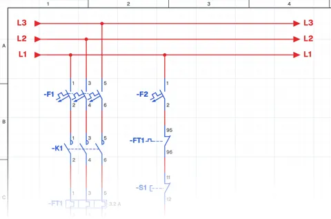 Delayed Stop Circuit with a Timer Relay
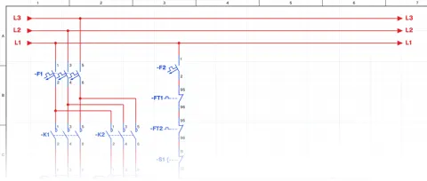 Sequential Induction Motor Starting and Delayed Stop with Timer Relays
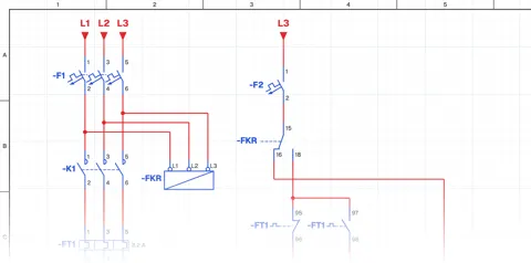 Direct-On-Line Starting Circuit with Protection and Indicator Lamps
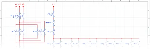 Automatic Motor Stopping at Set Positions with Sensors
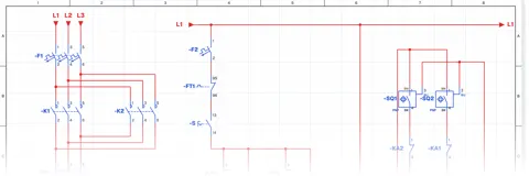 Forward–Reverse Motor Circuit with PNP Sensors
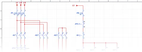 Star-Delta Starting Circuit for an Induction Motor
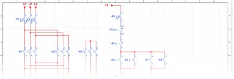 Star-Delta Starting Circuit with Forward–Reverse Control
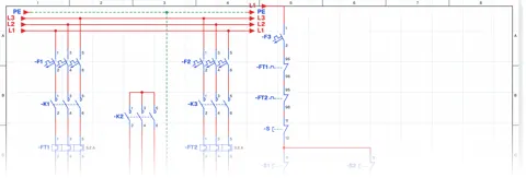 Dahlander Motor High Speed – Low Speed Circuit
Pump and level control
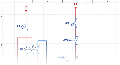 Automatic Pump Operation with an Upper-Level Float Switch
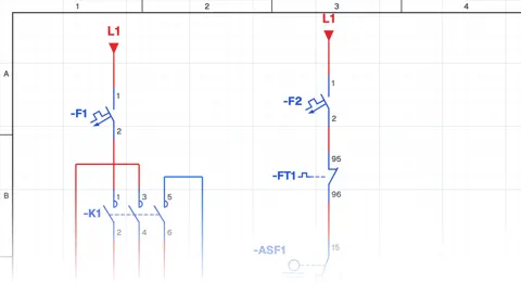 Automatic Pump Operation with a Lower-Level Float Switch
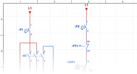 Automatic Tank Filling Control with Lower and Upper Float Switches
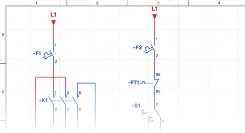 Manual and Automatic Pump Operation
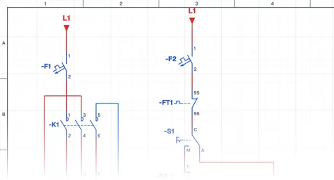 Manual Pump Operation with Self-Holding and Automatic Operation by Float Switch
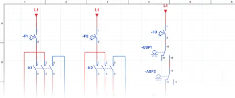 Running One of Two Pumps with a Selector Switch
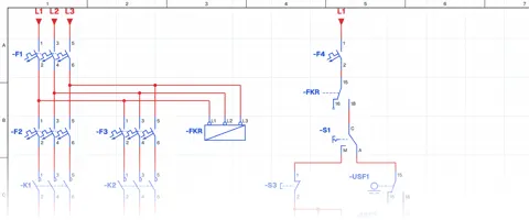 Two-Pump Level Control Circuit with Selector Switch and Phase Monitoring Relay
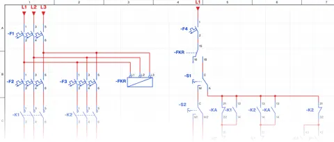 Float-Controlled Sequential Operation of Two Motors
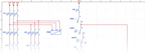 Float-Controlled Sequential Operation of Two Motors 2
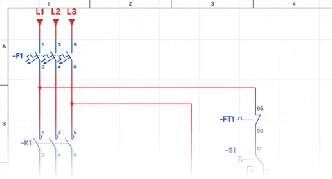 Manual and Automatic Pump Starting with Selector Switch and Float Switch (Contactor with Line-to-Line Coil)
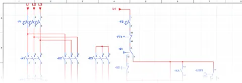 Manual and Automatic Star–Delta Starting with Float Switch – 1
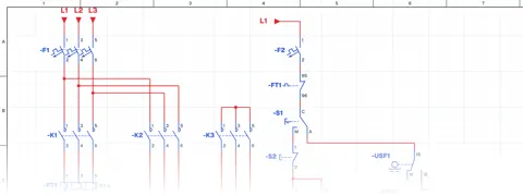 Manual and Automatic Star–Delta Starting with Float Switch – 2
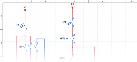 Liquid Level Relay – NO Contact Circuit Application
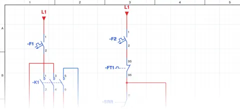 Liquid Level Relay – NC Contact Circuit Application
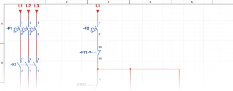 Liquid Level Relay – Two-Tank Water Transfer System
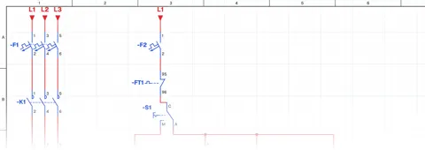 Manual and Automatic Pump Operation in a Two-Tank Water Transfer System with Liquid Level Relay
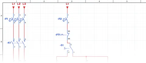 Manual and Automatic Pump Operation Using a Liquid Level Relay (NO Contact) and Float Switch
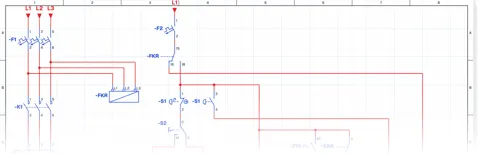 Manual and Automatic Pump Control with Signalling, Using a Liquid Level Relay (NO Contact) and Float Switch
Residual current protection
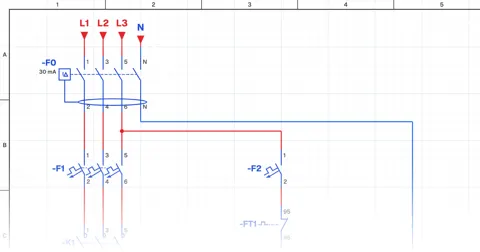
PLC circuits
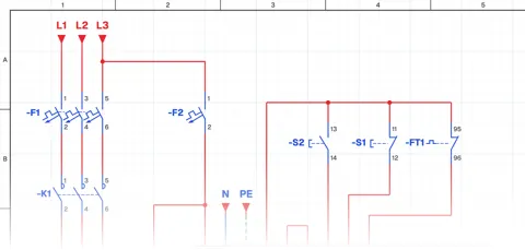 Start-Stop (Seal-in) with a PLC
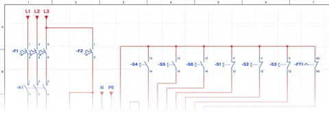 Start-Stop from Three Places with a PLC
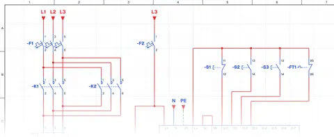 Interlocked Forward-Reverse with a PLC
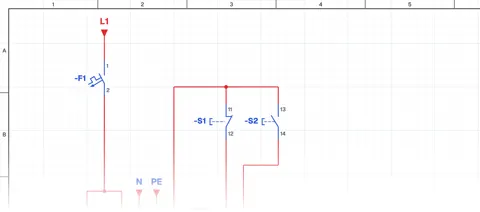 Traffic Light with a PLC
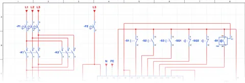 Garage Door with a PLC
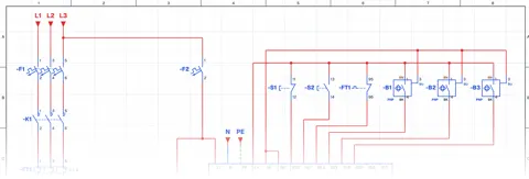 Box Size Sorting with a PLC
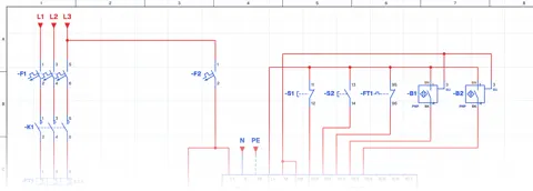 Tank Filling and Emptying with a PLC
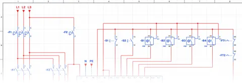 Double Conveyor with a PLC
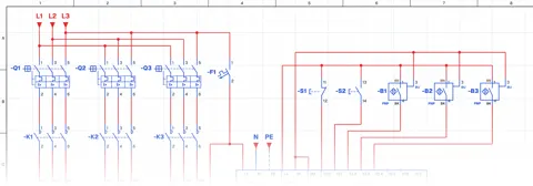 Two-Liquid Mixer with a PLC
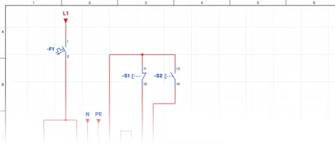 Four-Piston Sequence with a PLC
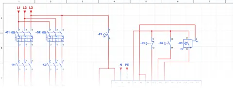 Box Sorter with a PLC
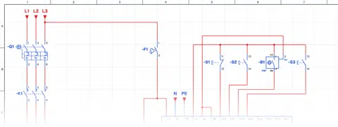 Production Line Counting with a PLC
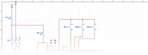 Single-Phase Motor with Three Switches
HMI
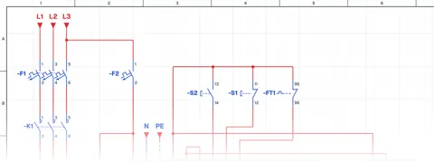
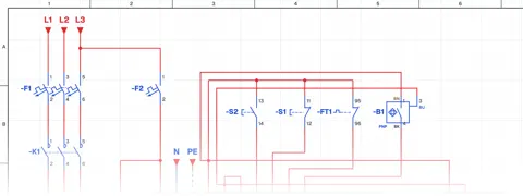
Frequency drive (VFD)
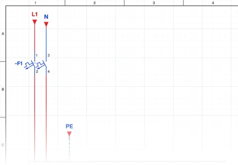 Running from the Keypad
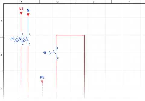 Two-Wire Run / Stop
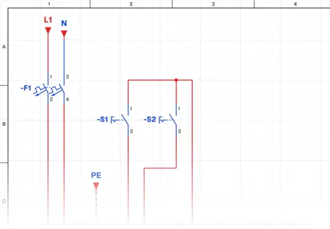 Run / Stop and Direction
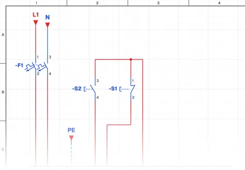 Three-Wire Start / Stop
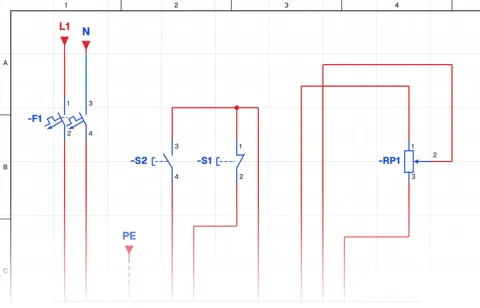 Speed Setting with a Potentiometer
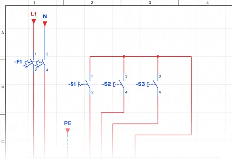 Electronic Potentiometer
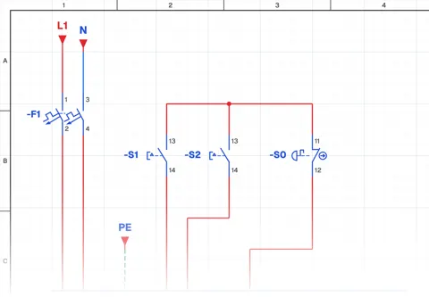 Forward - Reverse Operation