PLC circuits
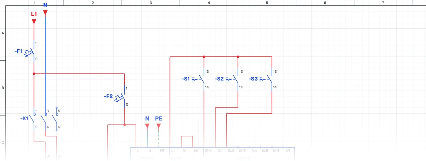
Single-Phase Motor with Three Switches
What is a single-phase motor with three switches?
It is a PLC logic application in which a single-phase motor runs for certain positions of three maintained switches. The eight possible states of the three switches are written into a truth table and the states in which the motor runs are turned into a program.
Where is it used?
The same logic is used on machines that depend on several safety and operating conditions: the machine runs only when the door is closed, there is pressure and the operator is ready. It is also used in PLC training to teach logic gates and Boolean algebra.
PLC wiring and ladder program
The switches go to PLC inputs and the motor contactor to an output. Each truth table row in which the motor runs becomes one branch in ladder, and the branches are connected in parallel.
What it teaches
Solving a problem with a truth table and turning it into a program is the most reliable way to program complex conditions without mistakes.
Parts used
- Circuit breaker (1-pole)
- F1, F2
- PLC
- PLC1
- Selector switch (NO)
- S1, S2, S3
Run it in the simulator.
This circuit is ready in the CoilPath library. Open it, press the buttons and follow the current. It also comes with a wiring view and a panel layout.