Pump and level control
Two-Pump Level Control Circuit with Selector Switch and Phase Monitoring Relay
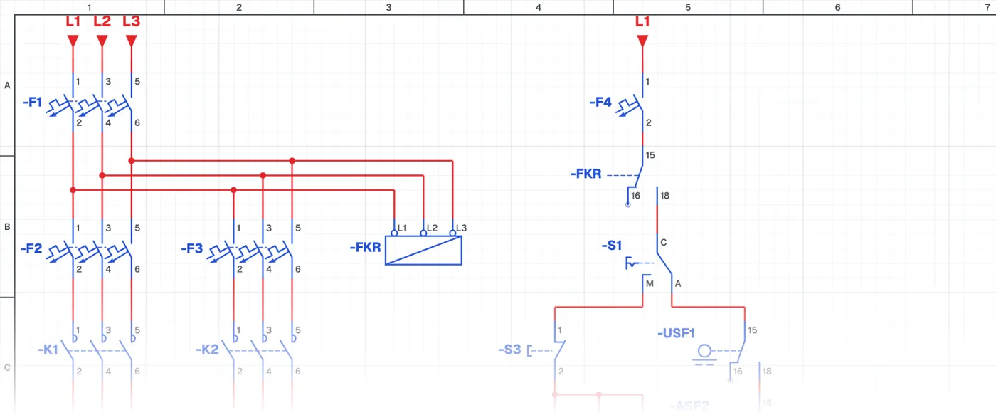
What is two-pump level control with a phase monitoring relay?
It is a complete pump control circuit in which two three-phase pumps run in manual or automatic mode, chosen with selector switches, and are protected by a phase monitoring relay. One switch selects the mode (manual-automatic), the other selects which pump runs. In automatic, float switches control the level.
Where is it used?
It is used in pump panels of large buildings, housing estates, hospitals, factories and municipal water systems. The phase monitoring relay stops the pumps on phase loss, wrong phase sequence and imbalance, keeping the motors from burning out. It is the typical control circuit of professional pump panels delivered on site.
Power circuit and control circuit
The power circuit has a main circuit breaker, a separate motor circuit breaker, contactor and overload relay for each pump, and the measuring terminals of the phase monitoring relay. In the control circuit the phase monitoring relay contact, the mode and pump selector switches, start-stop buttons and float switches work together.
What to watch out for
The phase monitoring relay is set for the supply voltage. The direction of the pump motors is checked on first start; the phase monitoring relay also guarantees the correct phase sequence.
Parts used
- Circuit breaker (3-pole)
- F1, F2, F3
- Overload relay
- FT1, FT2
- Motor 3~
- M1, M2
- MAN–AUTO selector switch
- S1, S2
- Float switch
- USF1, ASF2
- Contactor coil
- K1, K2
Run it in the simulator.
This circuit is ready in the CoilPath library. Open it, press the buttons and follow the current. It also comes with a wiring view and a panel layout.
Related circuits
- Float-Controlled Sequential Operation of Two Motors
- Float-Controlled Sequential Operation of Two Motors 2
- Manual and Automatic Pump Starting with Selector Switch and Float Switch (Contactor with Line-to-Line Coil)
- Manual and Automatic Star–Delta Starting with Float Switch – 1
- Manual and Automatic Star–Delta Starting with Float Switch – 2
- Liquid Level Relay – NO Contact Circuit Application