Pump and level control
Automatic Tank Filling Control with Lower and Upper Float Switches
What is tank filling with lower and upper float switches?
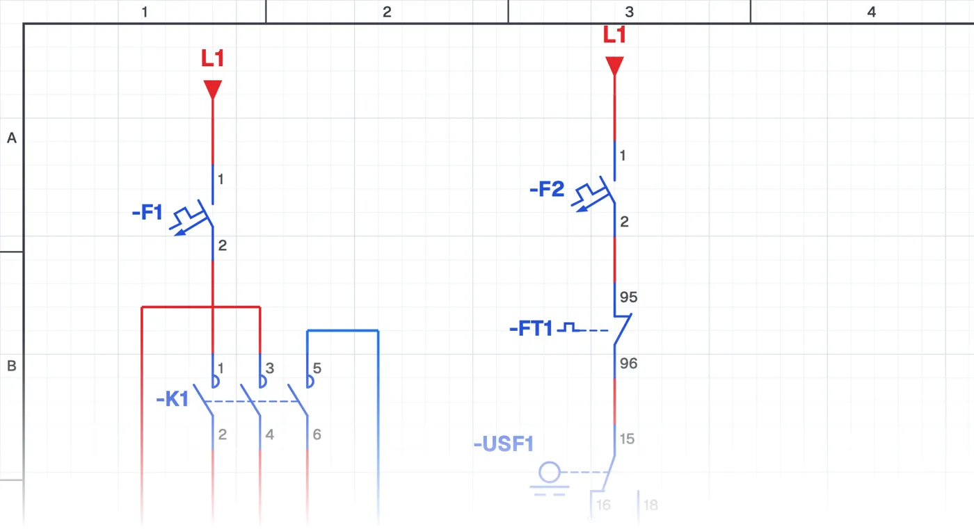
In this control circuit a tank is filled automatically with two float switches. The upper-level float switch fills the tank and prevents overflow; the lower-level float switch prevents the pump from running dry in the well or source tank it draws from. Together they protect both the tank and the pump.
Where is it used?
It is used in systems pumping from a well to a tank, buildings transferring water from a source tank to a roof tank, irrigation and livestock facilities. It is essential in summer, when well water drops and the pump could otherwise run dry and burn out.
Power circuit and control circuit
The power circuit is a single-phase pump motor with a circuit breaker, contactor and overload relay. The control circuit uses the contacts of both float switches together. How the float switches are connected to each other and which of their contacts are chosen decides whether the circuit works correctly.
What to watch out for
The lower float switch is hung above the pump inlet, so it cuts off at the level where the water can no longer feed the pump. On first start-up with an empty tank, check the state of the float switches.
Parts used
- Circuit breaker (1-pole)
- F1, F2
- Float switch
- USF1, ASF2
Run it in the simulator.
This circuit is ready in the CoilPath library. Open it, press the buttons and follow the current. It also comes with a wiring view and a panel layout.
Related circuits
- Manual and Automatic Pump Operation
- Manual Pump Operation with Self-Holding and Automatic Operation by Float Switch
- Running One of Two Pumps with a Selector Switch
- Two-Pump Level Control Circuit with Selector Switch and Phase Monitoring Relay
- Float-Controlled Sequential Operation of Two Motors
- Float-Controlled Sequential Operation of Two Motors 2