Motor control circuits
Sequential Induction Motor Starting and Delayed Stop with Timer Relays
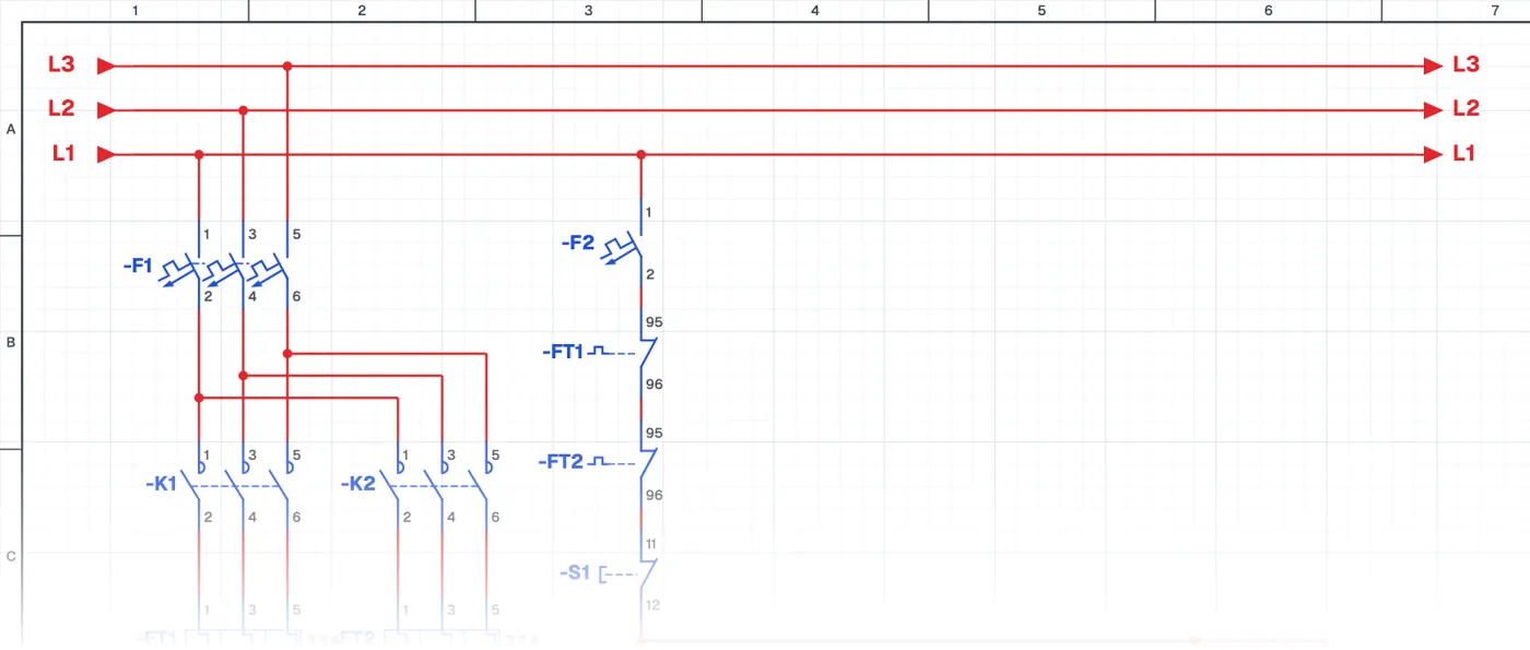
What is sequential starting with delayed stop?
In this control circuit motors start one after another and stop one after another after set delays. Several timer relays and an auxiliary relay work together, so the whole cycle runs by the set times without the operator stepping in.
Where is it used?
It is used on production lines with machines that feed each other, belt systems, crushing and screening plants and ventilation systems. On belt lines the order matters: the belt that receives the material starts first and stops last, so material does not pile up on the line.
Power circuit and control circuit
In the power circuit each motor has its own contactor and protection. The control circuit is an advanced structure in which timer relays and an auxiliary relay trigger each other. Anyone who can read this circuit can easily understand most time-controlled panels on site.
What to watch out for
Times are set for the process and each step is tested separately during commissioning. Always check that the stop button stops all motors safely, whichever step it is pressed in.
Parts used
- Overload relay
- FT1, FT2
- Motor 3~
- M1, M2
- Contactor coil
- K1, K2, KA
- Timer relay coil
- T1, T2, T3
Run it in the simulator.
This circuit is ready in the CoilPath library. Open it, press the buttons and follow the current. It also comes with a wiring view and a panel layout.
Related circuits
- Direct-On-Line Starting Circuit with Protection and Indicator Lamps
- Automatic Motor Stopping at Set Positions with Sensors
- Forward–Reverse Motor Circuit with PNP Sensors
- Star-Delta Starting Circuit for an Induction Motor
- Star-Delta Starting Circuit with Forward–Reverse Control
- Dahlander Motor High Speed – Low Speed Circuit