Motor control circuits
Delayed Stop Circuit with a Timer Relay
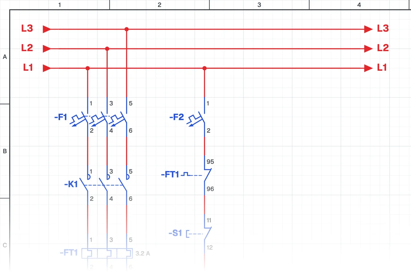
What is a delayed stop circuit?
In this control circuit the motor stops by itself when a set time has passed after starting. A timer relay counts the time. The operator can still stop the motor at any moment with the stop button.
Where is it used?
It is used for bathroom and toilet extractor fans, oven and drying fans, irrigation systems, mixers that must run for a set time and systems that work like a staircase timer. It is preferred wherever a process must finish in a fixed time or energy must not be wasted.
Power circuit and control circuit
The power circuit is a direct-on-line starter. The control circuit has a timer relay in addition to the contactor, and the timer's normally closed contact is used in the control circuit. It is a good example for understanding the difference between a timer's normally open and normally closed contacts.
What to watch out for
The timer is set to the running time the job needs. On multifunction timer relays, check that the correct function (on-delay) is selected.
Parts used
- Motor 3~
- M1
Run it in the simulator.
This circuit is ready in the CoilPath library. Open it, press the buttons and follow the current. It also comes with a wiring view and a panel layout.
Related circuits
- Sequential Induction Motor Starting and Delayed Stop with Timer Relays
- Direct-On-Line Starting Circuit with Protection and Indicator Lamps
- Automatic Motor Stopping at Set Positions with Sensors
- Forward–Reverse Motor Circuit with PNP Sensors
- Star-Delta Starting Circuit for an Induction Motor
- Star-Delta Starting Circuit with Forward–Reverse Control