Frequency drive (VFD)
Run / Stop and Direction
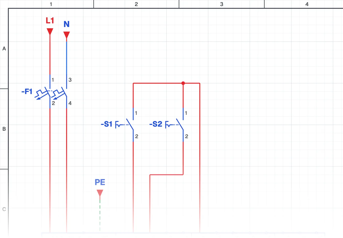
What is direction control on a frequency drive?
It is a connection in which the frequency drive is started with one switch and the motor's direction is changed with a second switch. When the direction changes, the drive first slows the motor down and stops it, then accelerates it the other way.
Where is it used?
It is used on reversing conveyors, mixers, doors and machine tools. It gives a much smoother change of direction than a contactor forward-reverse circuit and reduces mechanical stress.
Wiring and parameters
The two switches go to two digital inputs. Assigning the second input to direction is done with a parameter. If the parameter is not set correctly the input does nothing; this is a common mistake on site.
What to watch out for
On some machines, reverse rotation is dangerous (some pumps, for example). For such loads, reverse is disabled with a parameter.
Parts used
- Motor 3~
- M1
- Selector switch (NO)
- S1, S2
Run it in the simulator.
This circuit is ready in the CoilPath library. Open it, press the buttons and follow the current. It also comes with a wiring view and a panel layout.