Pump and level control
Float-Controlled Sequential Operation of Two Motors 2
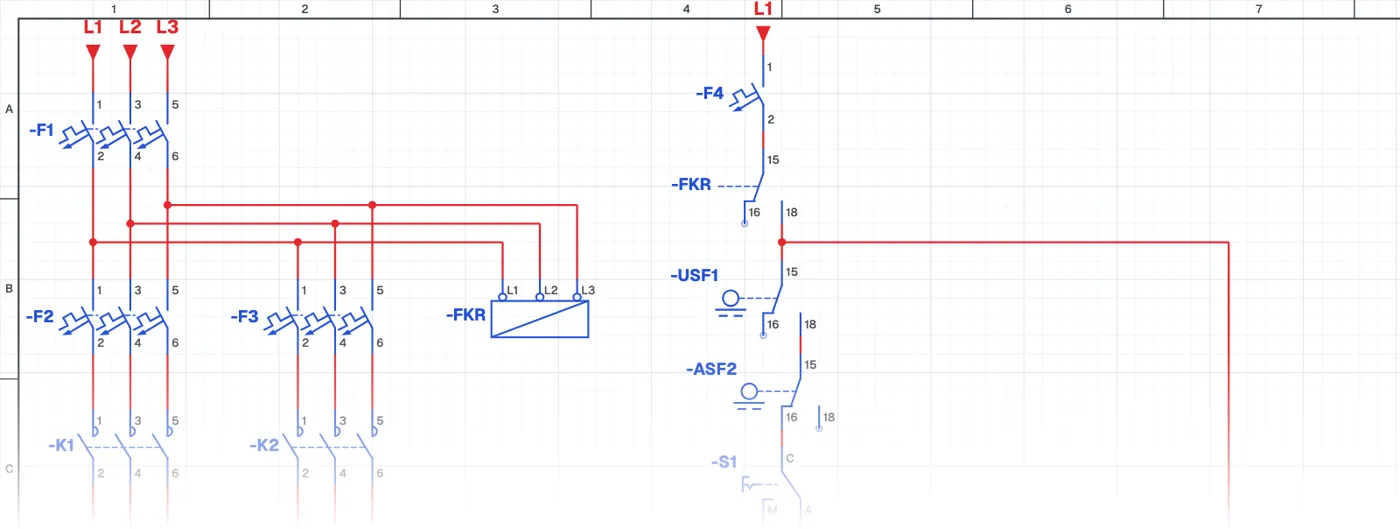
What is alternating operation of two pumps 2?
It is a different build of the alternating two-pump circuit. The result is the same; the difference is that the float switches are connected on another side of the control circuit.
Where is it used?
It is used in booster, circulation and drainage systems. On site you often meet different panel drawings that do the same job; reading this circuit next to the previous one makes it easier to understand how different designers solve the same problem.
Power circuit and control circuit
The power circuit is the same as the previous circuit. In the control circuit the float switches move, and this also changes how the auxiliary contactor is supplied. Placing the two drawings side by side shows how the position of one element in the control circuit affects the whole behaviour.
What to watch out for
When the float switches are on the phase side, their cables are live too; make sure the control supply is switched off before maintenance or replacing a float switch.
Parts used
- Circuit breaker (3-pole)
- F1, F2, F3
- Overload relay
- FT1, FT2
- Motor 3~
- M1, M2
- Float switch
- USF1, ASF2
- MAN–AUTO selector switch
- S1, S2
- Contactor coil
- K1, K2, KA
Run it in the simulator.
This circuit is ready in the CoilPath library. Open it, press the buttons and follow the current. It also comes with a wiring view and a panel layout.
Related circuits
- Manual and Automatic Pump Starting with Selector Switch and Float Switch (Contactor with Line-to-Line Coil)
- Manual and Automatic Star–Delta Starting with Float Switch – 1
- Manual and Automatic Star–Delta Starting with Float Switch – 2
- Liquid Level Relay – NO Contact Circuit Application
- Liquid Level Relay – NC Contact Circuit Application
- Liquid Level Relay – Two-Tank Water Transfer System