Motor control circuits
Sequential Induction Motor Starting with Timer Relays
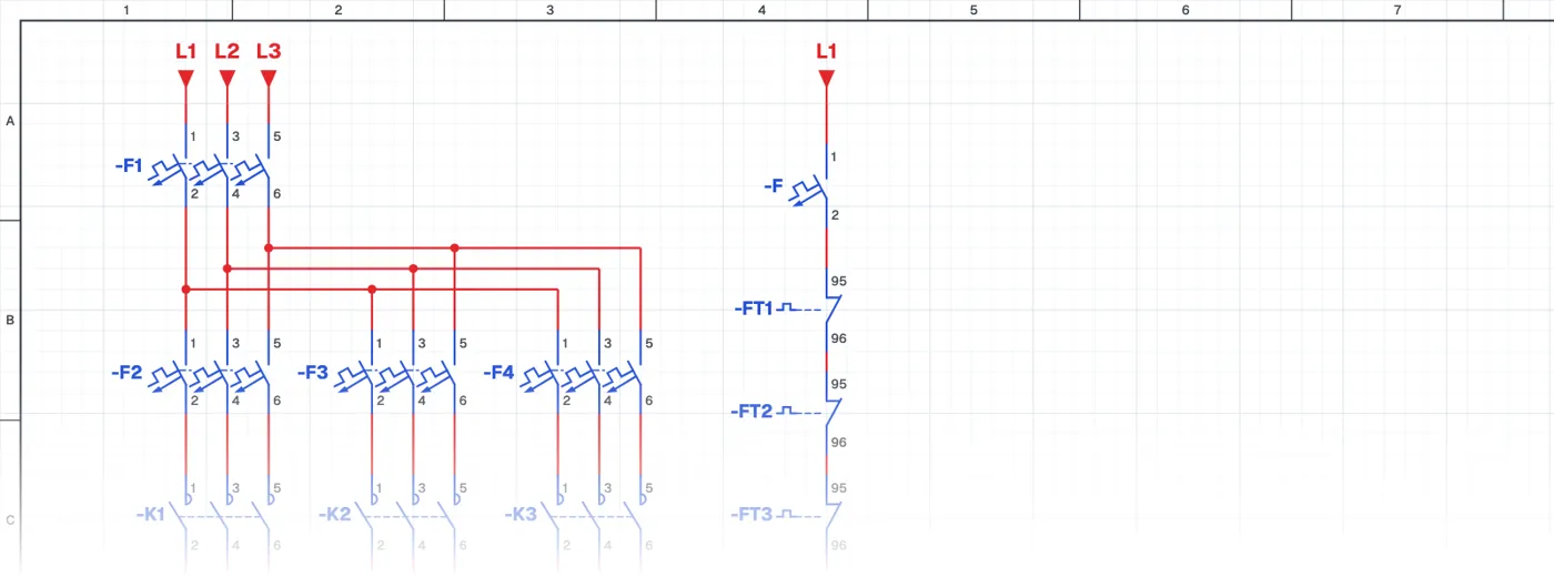
What is sequential motor starting with timer relays?
In this control circuit several motors start in a set order with an adjustable delay between them. The first motor starts with the start button and the next motors come in one after another when the timer relays time out. All motors stop together.
Where is it used?
It is used on conveyor and belt lines, ventilation and HVAC systems, linked production machines and large pump stations. Starting motors at the same moment draws a very high current from the supply; sequential starting spreads this inrush. On belt lines, running the belts in the right order also keeps material from piling up.
Power circuit and control circuit
In the power circuit each motor has its own contactor and overload relay. The control circuit adds timer relays next to the contactors. How the on-delay contact of a timer relay is used in the circuit is the key lesson of this circuit. The overload contacts make the whole system stop safely when one motor fails.
What to watch out for
The timer settings are chosen by how long each motor needs to reach speed and by what the process requires. The timer's supply voltage and contact type (on-delay) must match the schematic.
Parts used
- Circuit breaker (3-pole)
- F1, F2, F3, F4
- Overload relay
- FT1, FT2, FT3
- Motor 3~
- M1, M2, M3
- Contactor coil
- K1, K2, K3
- Timer relay coil
- T1, T2
Run it in the simulator.
This circuit is ready in the CoilPath library. Open it, press the buttons and follow the current. It also comes with a wiring view and a panel layout.
Related circuits
- Delayed Stop Circuit with a Timer Relay
- Sequential Induction Motor Starting and Delayed Stop with Timer Relays
- Direct-On-Line Starting Circuit with Protection and Indicator Lamps
- Automatic Motor Stopping at Set Positions with Sensors
- Forward–Reverse Motor Circuit with PNP Sensors
- Star-Delta Starting Circuit for an Induction Motor