Motor control circuits
Contactor Connection with a Phase-to-Phase Coil
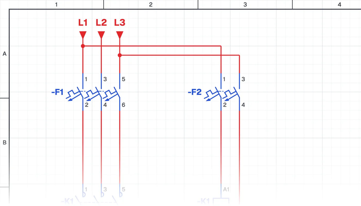
What is a phase-to-phase contactor coil?
Both ends of the contactor coil are connected to two different phases. The coil works at line-to-line voltage and the control circuit uses no neutral.
Where is it used?
This connection is common in installations without a neutral in the panel, in older industrial panels, on some imported machines and in motor panels supplied with three phases only. When troubleshooting or renewing an old panel you need to know which voltage feeds the coil.
Power circuit and control circuit
The power circuit is the same as with a phase-neutral coil: three phases go through the circuit breaker and the contactor's main contacts to the motor. The difference is in the control circuit, where the coil is connected to two phases through a two-pole circuit breaker that switches both ends of the control circuit together.
What to watch out for
The coil voltage must match the line-to-line voltage; a phase-neutral coil burns out quickly in this connection. Other control devices such as indicator lamps or timer relays must also suit the same voltage.
Parts used
- Motor 3~
- M1
Run it in the simulator.
This circuit is ready in the CoilPath library. Open it, press the buttons and follow the current. It also comes with a wiring view and a panel layout.
Related circuits
- Direct-On-Line Starting Circuit for an Induction Motor
- Induction Motor Jog (Inching) Circuit
- Seal-in Circuit (Continuous Running of an Induction Motor)
- Seal-in Circuit (Continuous Running of an Induction Motor with a Relay)
- Jog Button with Momentary Running and Seal-in Cancel Circuit
- Seal-in Circuit with Start–Stop Control from Three Locations