Pump and level control
Automatic Pump Operation with a Lower-Level Float Switch
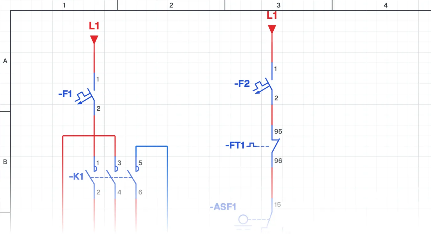
What is a drainage pump circuit with a float switch?
In this control circuit a drainage (sump) pump runs by itself with a float switch placed in the pit. When the water level rises the pump runs and empties the pit; when the water goes down it stops.
Where is it used?
It is used in rain and seepage pits in basements, lift pits, car park ramps, septic and wastewater pits, construction sites and agricultural drainage channels. It is one of a building's most important automatic protections against flooding.
Power circuit and control circuit
The power circuit is a single-phase pump motor with a circuit breaker, contactor and overload relay. The control circuit uses a float switch contact; the difference from the filling circuit is that the other contact of the float switch is used. Being able to fill or empty with the same float switch shows why choosing the right contact matters.
What to watch out for
Running dry is the most common cause of drainage pump failures; the float switch must cut off before the water drops below the pump's suction. In wastewater pits, the float cable must move freely without catching on anything.
Parts used
- Circuit breaker (1-pole)
- F1, F2
- Float switch
- ASF1
Run it in the simulator.
This circuit is ready in the CoilPath library. Open it, press the buttons and follow the current. It also comes with a wiring view and a panel layout.
Related circuits
- Automatic Tank Filling Control with Lower and Upper Float Switches
- Manual and Automatic Pump Operation
- Manual Pump Operation with Self-Holding and Automatic Operation by Float Switch
- Running One of Two Pumps with a Selector Switch
- Two-Pump Level Control Circuit with Selector Switch and Phase Monitoring Relay
- Float-Controlled Sequential Operation of Two Motors