Pump and level control
Manual and Automatic Pump Starting with Selector Switch and Float Switch (Contactor with Line-to-Line Coil)
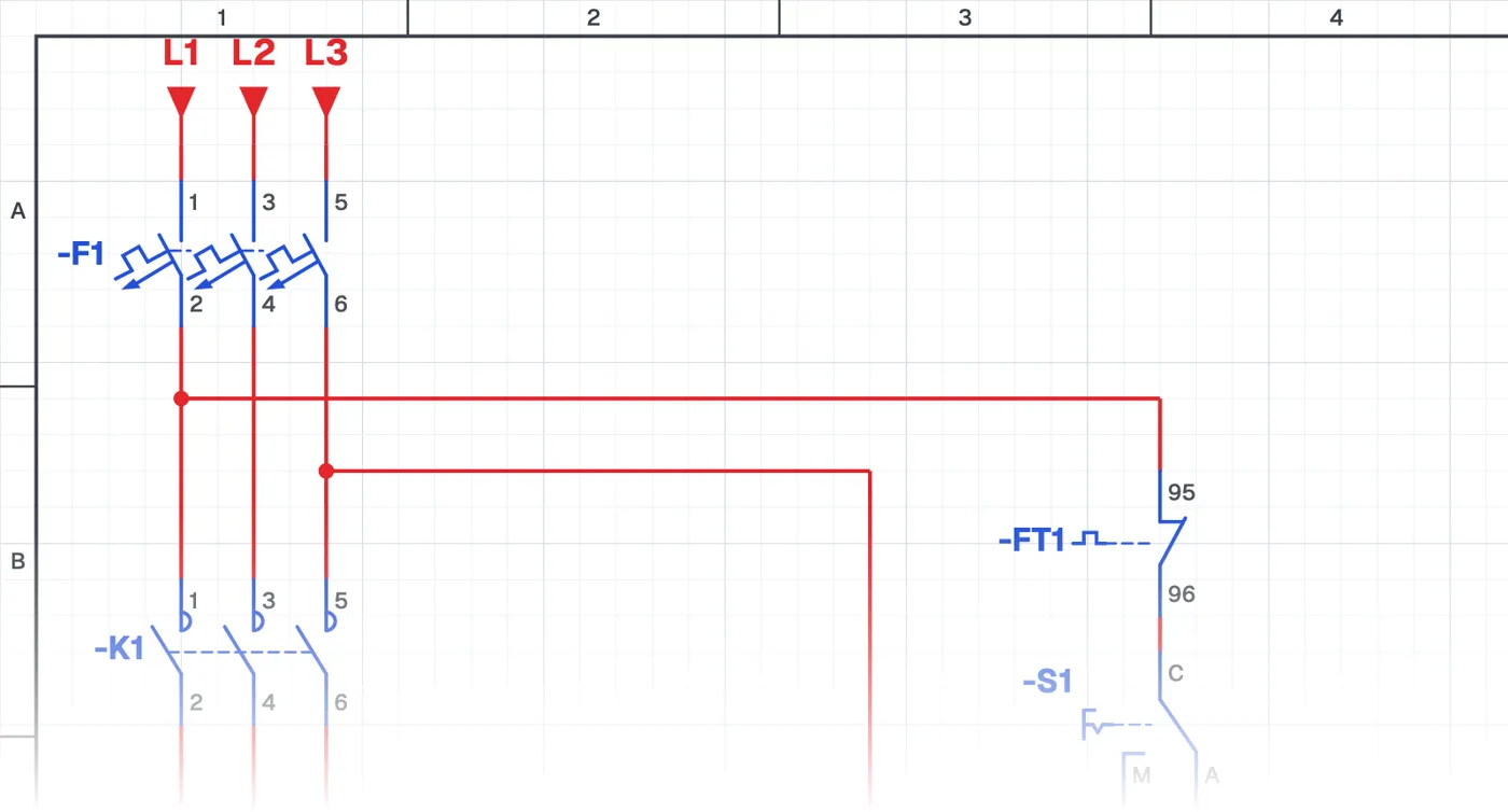
What is a manual-automatic pump circuit with a line-to-line coil?
It is a single-pump circuit that runs in manual or automatic mode with a selector switch and float switch, but with no neutral in the control circuit. The contactor coil is supplied between two phases.
Where is it used?
It is used at irrigation wells without a neutral in the panel, in older industrial plants and at pump stations supplied with three phases only. This connection is common in pump panels at the wellhead.
Power circuit and control circuit
The power circuit is a three-phase pump motor with a circuit breaker, contactor and overload relay. The control circuit is built between two phases; the selector switch, float switch and overload contact all sit between them. The coil voltage must match the line-to-line voltage.
What to watch out for
Every device in the control circuit (coil, indicator lamp, timer relay) must suit the line-to-line voltage. A contactor with a phase-neutral coil burns out quickly in this circuit.
Parts used
- Motor 3~
- M1
- Float switch
- USF1
Run it in the simulator.
This circuit is ready in the CoilPath library. Open it, press the buttons and follow the current. It also comes with a wiring view and a panel layout.
Related circuits
- Manual and Automatic Star–Delta Starting with Float Switch – 1
- Manual and Automatic Star–Delta Starting with Float Switch – 2
- Liquid Level Relay – NO Contact Circuit Application
- Liquid Level Relay – NC Contact Circuit Application
- Liquid Level Relay – Two-Tank Water Transfer System
- Manual and Automatic Pump Operation in a Two-Tank Water Transfer System with Liquid Level Relay