Pump and level control
Manual and Automatic Pump Operation
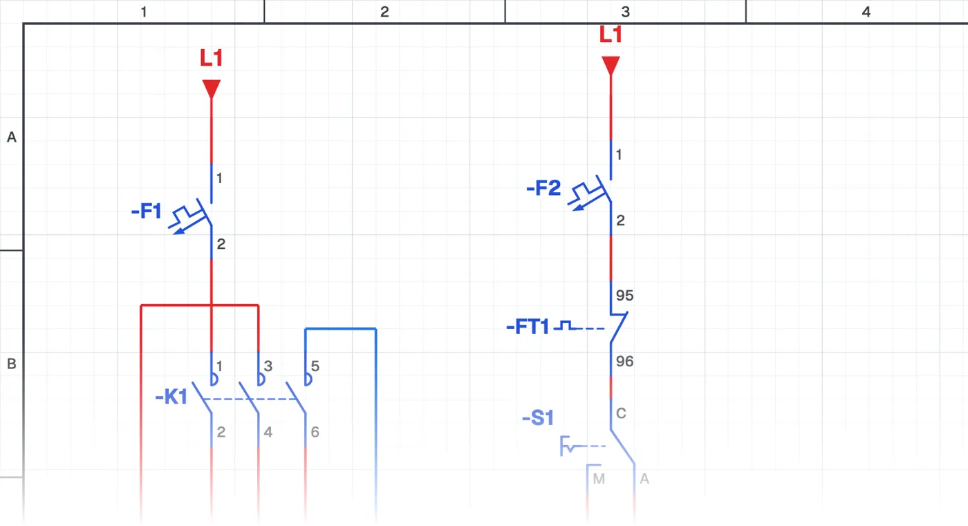
What is a manual and automatic pump circuit?
In this control circuit the pump can run in manual or automatic mode, chosen with a selector switch (MAN-0-AUTO). In automatic the float switches control the pump; in manual the float switches are bypassed and the pump runs regardless of the level.
Where is it used?
It is used in building and housing estate pump panels, booster systems, irrigation and industrial pump panels. Manual operation is needed for maintenance, testing, float switch faults and emergencies. Most pump panels delivered on site have a MAN-AUTO selector switch.
Power circuit and control circuit
The power circuit is the pump motor's circuit breaker, contactor and overload relay. In the control circuit the selector switch feeds two separate branches: one through the float switches, the other directly to the contactor. Reading selector switch contacts is the basis of troubleshooting pump panels.
What to watch out for
Remember that in manual the pump runs regardless of the level; a pump left in manual for a long time can run dry or overflow the tank. That is why manual is usually used only for short operations.
Parts used
- Circuit breaker (1-pole)
- F1, F2
- Float switch
- USF1, ASF2
Run it in the simulator.
This circuit is ready in the CoilPath library. Open it, press the buttons and follow the current. It also comes with a wiring view and a panel layout.
Related circuits
- Manual Pump Operation with Self-Holding and Automatic Operation by Float Switch
- Running One of Two Pumps with a Selector Switch
- Two-Pump Level Control Circuit with Selector Switch and Phase Monitoring Relay
- Float-Controlled Sequential Operation of Two Motors
- Float-Controlled Sequential Operation of Two Motors 2
- Manual and Automatic Pump Starting with Selector Switch and Float Switch (Contactor with Line-to-Line Coil)