PLC circuits
Garage Door with a PLC
What is a garage door with a PLC?
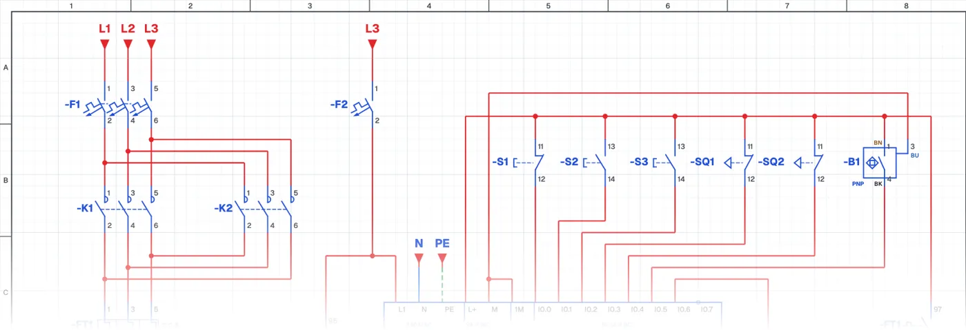
It is an automation application in which a garage or industrial door is opened and closed by a PLC. The door motor runs forward and reverse; upper and lower limit switches stop the door at its end positions, and a photocell reopens the door if an obstacle enters while it is closing.
Where is it used?
It is used on car park, housing estate, factory and warehouse doors, sectional and roller doors and barriers. The same logic applies to every moving system that must stop at end positions and be protected by a safety sensor.
PLC wiring and ladder program
The power circuit is an interlocked forward-reverse circuit. Buttons, limit switches and the photocell go to PLC inputs; the open and close contactors to PLC outputs. The overload contact is wired to the common terminal of the outputs, giving protection at hardware level too.
Safety
With automatic doors, keeping people and vehicles from harm comes first. The photocell and limit switches must be wired correctly and the program must give priority to safety.
Parts used
- Motor 3~
- M1
- PLC
- PLC1
- Start button (NO)
- S2, S3
- Limit switch (NC)
- SQ1, SQ2
- Contactor coil
- K1, K2
Run it in the simulator.
This circuit is ready in the CoilPath library. Open it, press the buttons and follow the current. It also comes with a wiring view and a panel layout.