Frequency drive (VFD)
Two-Wire Run / Stop
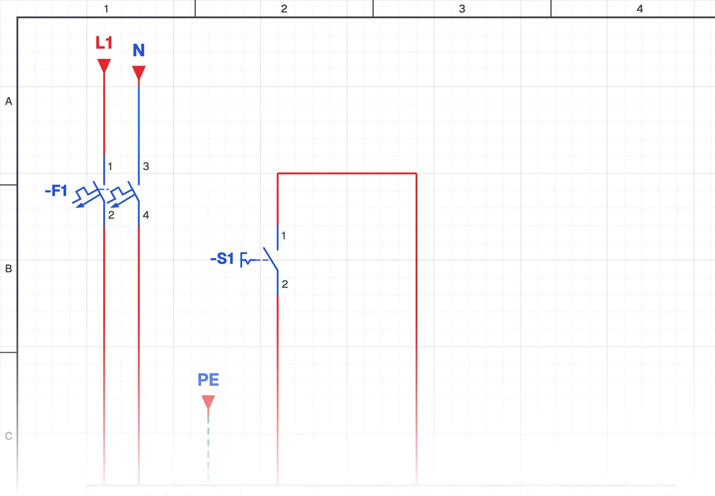
What is two-wire run/stop on a frequency drive?
It is a connection in which the frequency drive is started and stopped with a single switch through a digital input. The motor runs while the switch is closed and stops when it opens. This is called two-wire (2-wire) control.
Where is it used?
It is used on continuously running loads such as pumps and fans, and in systems where a thermostat, pressure switch or PLC output runs the drive. It is the simplest form of remote control.
Wiring and parameters
The switch is wired between a digital input and the common terminal of the drive. Setting the drive to remote operation and assigning the input to run/stop is done with parameters. Whether the inputs work with NPN or PNP logic depends on the drive.
What to watch out for
With two-wire control, if the switch is closed when power returns after an outage, the motor starts by itself. On machines where this is dangerous, three-wire control is preferred.
Parts used
- Motor 3~
- M1
Run it in the simulator.
This circuit is ready in the CoilPath library. Open it, press the buttons and follow the current. It also comes with a wiring view and a panel layout.