Pump and level control
Manual Pump Operation with Self-Holding and Automatic Operation by Float Switch
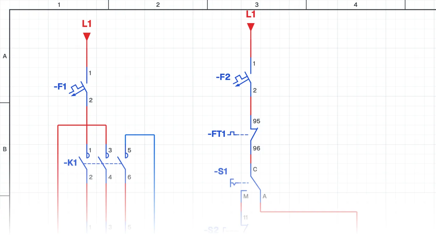
What is a manual pump circuit with seal-in and float switch automatic?
It is a manual-automatic pump circuit with start-stop buttons and a seal-in added to the manual side. In manual the operator starts the pump with the start button and stops it with the stop button; in automatic the float switches take over.
Where is it used?
It is widely used in pump panels of buildings, housing estates, hotels and factories. Controlling the pump with buttons in manual is safer than running it with the selector switch: when power returns after an outage, the pump does not restart by itself in manual.
Power circuit and control circuit
The power circuit is the pump motor, circuit breaker, contactor and overload relay. The control circuit consists of the selector switch, start-stop buttons, seal-in contact and float switches. It shows how a seal-in circuit and level control combine in one circuit.
What to watch out for
Check that the overload relay protects the pump in both manual and automatic operation. Button and selector switch labels should be clearly marked on the panel door.
Parts used
- Circuit breaker (1-pole)
- F1, F2
- Float switch
- USF1, ASF2
Run it in the simulator.
This circuit is ready in the CoilPath library. Open it, press the buttons and follow the current. It also comes with a wiring view and a panel layout.
Related circuits
- Running One of Two Pumps with a Selector Switch
- Two-Pump Level Control Circuit with Selector Switch and Phase Monitoring Relay
- Float-Controlled Sequential Operation of Two Motors
- Float-Controlled Sequential Operation of Two Motors 2
- Manual and Automatic Pump Starting with Selector Switch and Float Switch (Contactor with Line-to-Line Coil)
- Manual and Automatic Star–Delta Starting with Float Switch – 1