Pump and level control
Running One of Two Pumps with a Selector Switch
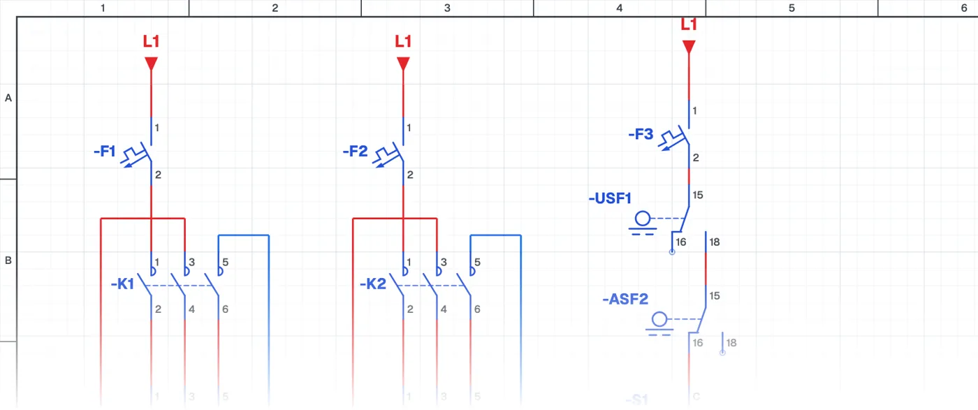
What is a two-pump circuit with a selector switch?
In a two-pump system, this control circuit uses a selector switch to choose which pump runs. Only one pump runs at a time. Each pump has its own contactor and overload relay, and the level is controlled with float switches.
Where is it used?
It is used for duty-standby operation in booster systems, building water supply, circulation and irrigation systems. When one pump fails or is under maintenance, the system keeps running with the other and the water supply is not interrupted.
Power circuit and control circuit
In the power circuit the two pump motors are supplied through separate contactors and overload relays. The control circuit has the float switches, the pump selector switch and two contactors. Each overload relay stopping only its own pump is a basic rule of redundant systems.
What to watch out for
Both pumps need to run regularly; a standby pump that never runs may be seized when it is needed. That is why pumps are swapped at intervals or an automatic alternating circuit is used.
Parts used
- Circuit breaker (1-pole)
- F1, F2, F3
- Overload relay
- FT1, FT2
- Single-phase motor
- M1, M2
- Float switch
- USF1, ASF2
- Contactor coil
- K1, K2
Run it in the simulator.
This circuit is ready in the CoilPath library. Open it, press the buttons and follow the current. It also comes with a wiring view and a panel layout.
Related circuits
- Two-Pump Level Control Circuit with Selector Switch and Phase Monitoring Relay
- Float-Controlled Sequential Operation of Two Motors
- Float-Controlled Sequential Operation of Two Motors 2
- Manual and Automatic Pump Starting with Selector Switch and Float Switch (Contactor with Line-to-Line Coil)
- Manual and Automatic Star–Delta Starting with Float Switch – 1
- Manual and Automatic Star–Delta Starting with Float Switch – 2