Pump and level control
Float-Controlled Sequential Operation of Two Motors
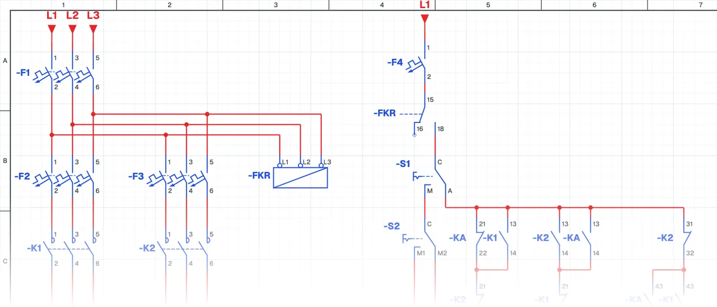
What is float-controlled alternating operation of two pumps?
In this control circuit two pumps take turns (alternate) in each operating cycle. The tank is filled once with the first pump and the next time with the second. An auxiliary contactor remembers whose turn it is.
Where is it used?
It is used in booster and circulation systems, building water supply, wastewater and drainage stations. Because the pumps run for equal time they wear evenly, both last longer, and the standby pump does not seize from standing idle.
Power circuit and control circuit
The power circuit has two pump motors with their contactors and overload relays, and a phase monitoring relay. The control circuit has float switches, the auxiliary contactor, interlock contacts and a manual-automatic selector switch. How the turn is remembered with relay logic is a fine example of automation without a PLC.
What to watch out for
During commissioning, several filling cycles are watched to check that the pumps really alternate. The interlock between the two contactors is also tested.
Parts used
- Circuit breaker (3-pole)
- F1, F2, F3
- Overload relay
- FT1, FT2
- Motor 3~
- M1, M2
- MAN–AUTO selector switch
- S1, S2
- Contactor coil
- K1, K2, KA
- Float switch
- ASF2, USF1
Run it in the simulator.
This circuit is ready in the CoilPath library. Open it, press the buttons and follow the current. It also comes with a wiring view and a panel layout.
Related circuits
- Float-Controlled Sequential Operation of Two Motors 2
- Manual and Automatic Pump Starting with Selector Switch and Float Switch (Contactor with Line-to-Line Coil)
- Manual and Automatic Star–Delta Starting with Float Switch – 1
- Manual and Automatic Star–Delta Starting with Float Switch – 2
- Liquid Level Relay – NO Contact Circuit Application
- Liquid Level Relay – NC Contact Circuit Application