Motor control circuits
Forward–Reverse Motor Circuit with PNP Sensors
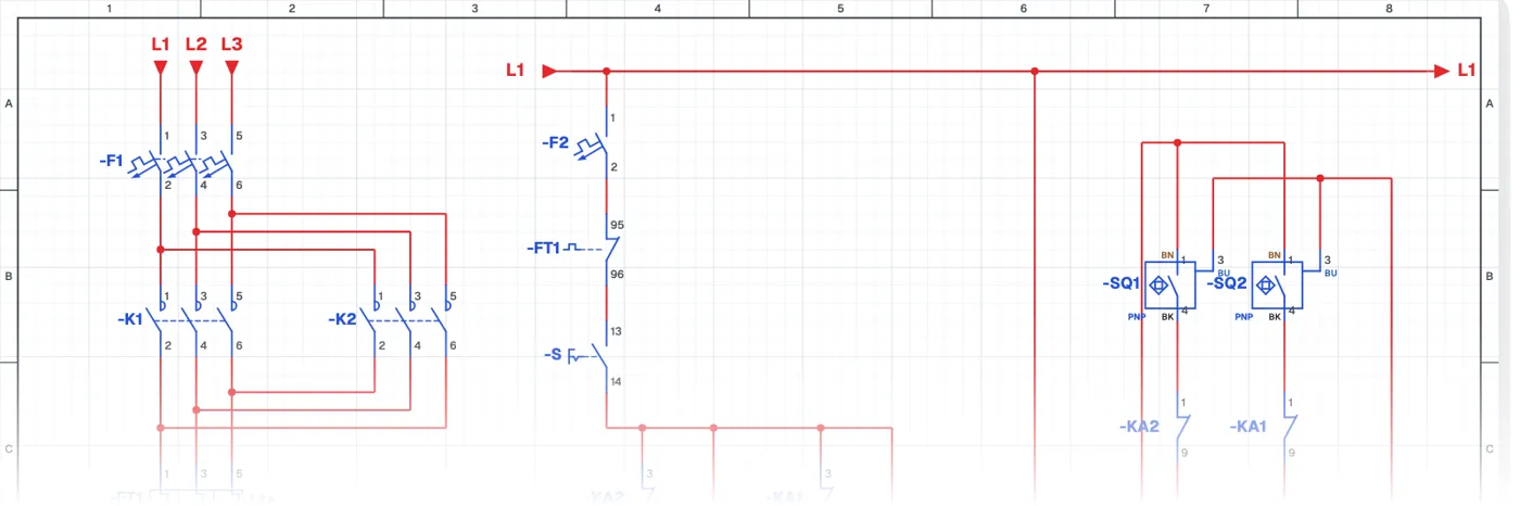
What is a forward-reverse circuit with PNP sensors?
In this control circuit the motor moves forward and back by itself thanks to PNP sensors at the two ends. When the sensor at one end detects the load the motor turns one way, and when the sensor at the other end detects it the motor turns the other way. The system is enabled with a selector switch.
Where is it used?
It is used on transfer carts moving between two points, automatic doors, moving fixtures in blasting and paint booths and test rigs. Sensor-based reversing is one of the most basic automation applications.
Power circuit and control circuit
The power circuit is the same as the forward-reverse circuit. In the control circuit the sensors and auxiliary relays are supplied with 24 V DC from an AC-DC converter, while the contactors are supplied from phase and neutral. Using DC and AC control together in one panel is very common on site.
PNP vs NPN sensors
A PNP sensor switches plus (+) to its output when it detects, an NPN sensor switches minus (−). The sensor type must suit the relay or PLC input it is connected to. PNP sensors are more common in Europe and Turkey.
Parts used
- Motor 3~
- M1
- Contactor coil
- K1, K2, KA1, KA2
- Sensor (3-wire)
- SQ1, SQ2
Run it in the simulator.
This circuit is ready in the CoilPath library. Open it, press the buttons and follow the current. It also comes with a wiring view and a panel layout.