PLC circuits
Traffic Light with a PLC
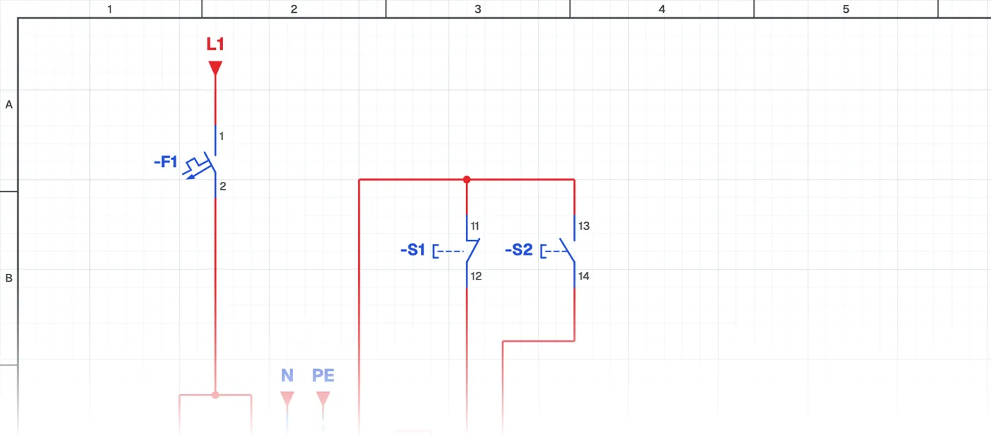
What is a traffic light with a PLC?
It is an application in which the red, red-amber, green and amber sequence of a traffic light is made with PLC timers. The start button starts the system, the stop button stops it, and the cycle repeats by itself.
Where is it used?
The traffic light is one of the best-known PLC training examples. The same structure is used in all sequential, timed systems in factories: washing machines, filling lines, heat treatment ovens and step-by-step machines.
PLC wiring and ladder program
The lamps go to PLC outputs, the buttons to inputs. In the program, on-delay timers (TON) start each other in turn and the last timer restarts the cycle. How to write the program when one output must stay on across several steps is what this application teaches.
What it teaches
Chaining timers is the basis of sequential control. Once this logic is learned, programs for multi-step machines become easy to read.
Parts used
- PLC
- PLC1
- Indicator lamp
- H1, H2, H3
Run it in the simulator.
This circuit is ready in the CoilPath library. Open it, press the buttons and follow the current. It also comes with a wiring view and a panel layout.