Pump and level control
Manual and Automatic Pump Operation Using a Liquid Level Relay (NO Contact) and Float Switch
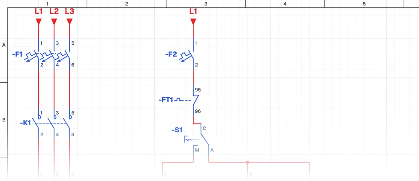
What is a pump circuit with a liquid level relay and float switch?
It is a manual-automatic pump circuit for a two-tank transfer system that uses a liquid level relay in the source tank and a float switch in the target tank. It shows different level sensing devices used together in one circuit.
Where is it used?
When the source is a narrow well or borehole, electrodes are used; when the target is a wide roof or building tank, a float switch is used. On site, mixed systems like this are often the most suitable and economical solution.
Power circuit and control circuit
The power circuit is the pump motor, circuit breaker, contactor and overload relay. The control circuit has the liquid level relay contact, the float switch contact, the selector switch and start-stop buttons. The float switch contact is chosen so that it prevents overflow in the target tank.
What to watch out for
The level ranges of the float switch and the electrodes are set independently. During commissioning, the full and empty states of both tanks are tested separately.
Parts used
- Motor 3~
- M1
- Float switch
- SF1
Run it in the simulator.
This circuit is ready in the CoilPath library. Open it, press the buttons and follow the current. It also comes with a wiring view and a panel layout.
Related circuits
- Manual and Automatic Pump Control with Signalling, Using a Liquid Level Relay (NO Contact) and Float Switch
- Automatic Pump Operation with an Upper-Level Float Switch
- Automatic Pump Operation with a Lower-Level Float Switch
- Automatic Tank Filling Control with Lower and Upper Float Switches
- Manual and Automatic Pump Operation
- Manual Pump Operation with Self-Holding and Automatic Operation by Float Switch