Frequency drive (VFD)
Electronic Potentiometer
What is an electronic potentiometer (motor potentiometer)?
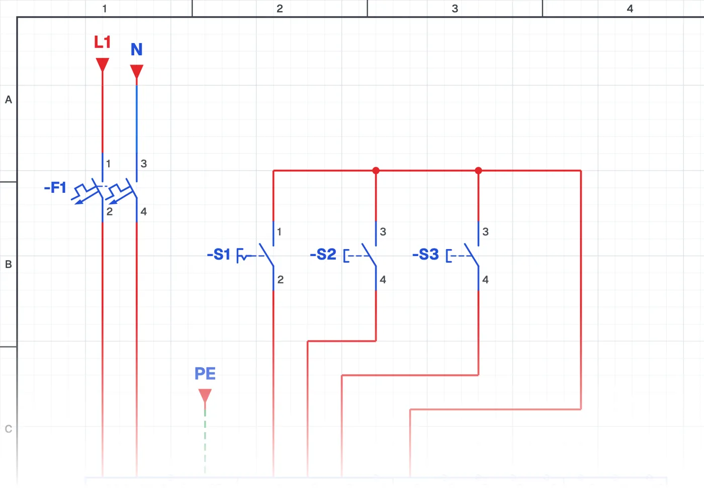
It is a speed setting method in which the motor speed is raised and lowered with two buttons. While one button is held the speed rises, while the other is held it falls; when the buttons are released the motor keeps that speed. No potentiometer is needed.
Where is it used?
It is used on machines that need remote speed setting, when space on the operator panel is limited, and in systems where speed must be changed by PLC outputs. The buttons can be on a control desk with the drive in a distant panel.
Wiring and parameters
The run/stop, speed up and speed down buttons go to three separate digital inputs. Selecting the electronic potentiometer as speed reference and assigning the inputs is done with parameters.
What to watch out for
Some drives clear the last speed when power fails, others keep it; this behaviour is chosen with a parameter.
Parts used
- Motor 3~
- M1
- Start button (NO)
- S2, S3
Run it in the simulator.
This circuit is ready in the CoilPath library. Open it, press the buttons and follow the current. It also comes with a wiring view and a panel layout.