Frequency drive (VFD)
Speed Setting with a Potentiometer
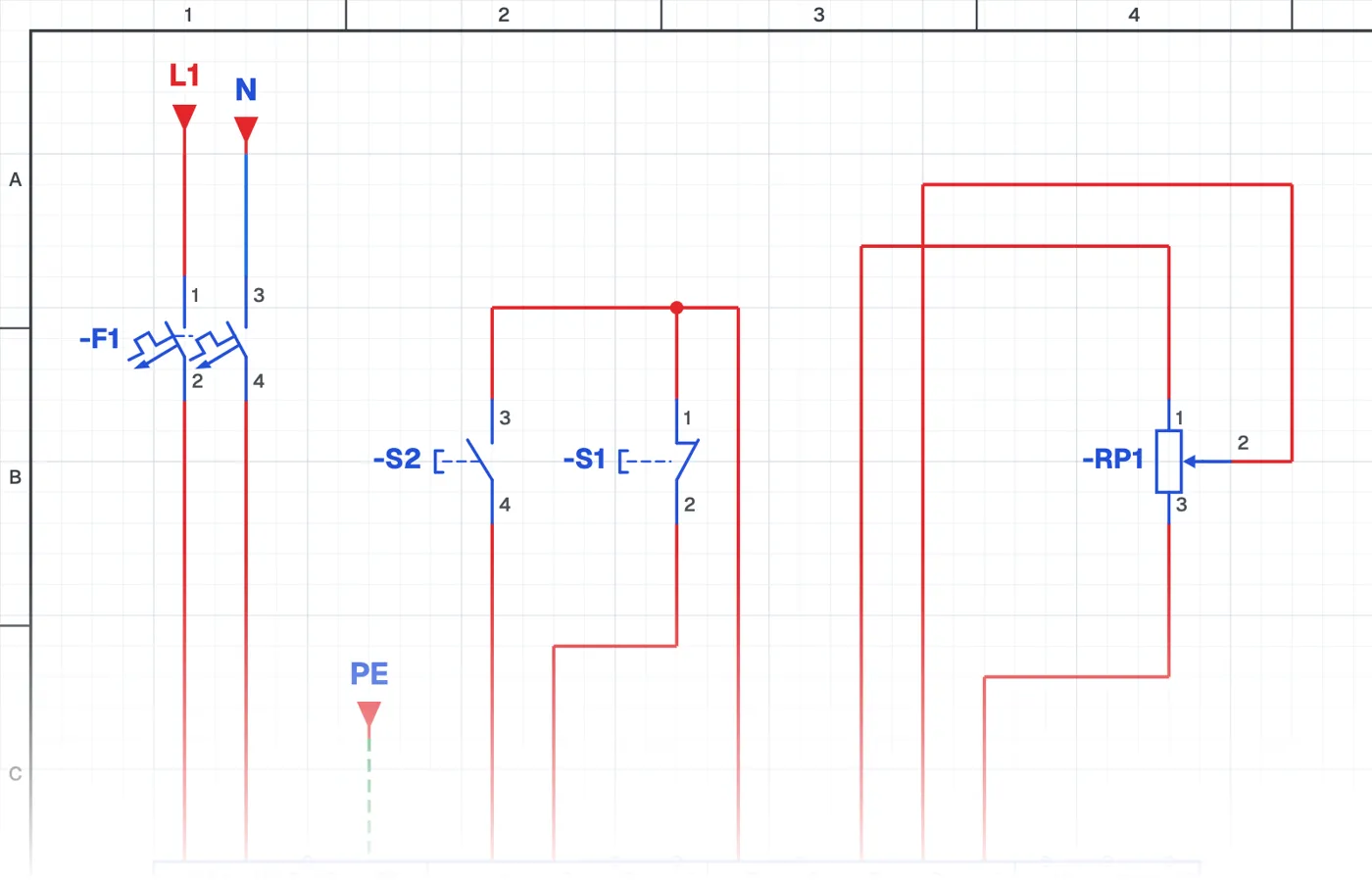
What is speed control with a potentiometer?
It is a connection in which the motor speed is set with a potentiometer wired to the drive's analog input. As the potentiometer is turned, the motor frequency changes between the set minimum and maximum.
Where is it used?
It is used on fans, pumps, conveyors, mixers and feeders, wherever the operator must change the speed easily from the panel. It is the most common speed setting method.
Wiring and parameters
The three ends of the potentiometer go to the drive's reference voltage, analog input and common terminals. Taking the speed reference from the analog input and the minimum-maximum frequency limits are set with parameters.
What to watch out for
Analog signal cables pick up interference; use shielded cable and lay it apart from power cables. Do not set the minimum frequency below the point where the motor's own fan can still cool it enough.
Parts used
- Motor 3~
- M1
Run it in the simulator.
This circuit is ready in the CoilPath library. Open it, press the buttons and follow the current. It also comes with a wiring view and a panel layout.