Motor control circuits
Automatic Motor Stopping at Set Positions with Sensors
What is automatic stopping with sensors?
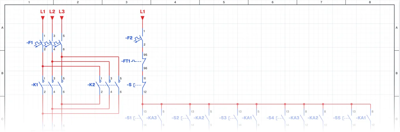
In this control circuit the motor stops by itself at the desired position thanks to inductive sensors placed at set points. The operator selects the target position; when the motor gets there, the sensor detects metal and the motor stops. Contactors for forward and reverse, auxiliary relays and sensors work together.
Where is it used?
It is used on rotary tables, indexing tables, positioning systems, valve and damper actuators and mechanisms that must stop at given angles. Using contactless sensors instead of limit switches removes mechanical wear.
Power circuit and control circuit
The power circuit is a forward-reverse circuit. The control circuit combines auxiliary relays, sensor outputs and the contactors' interlock contacts. Wiring sensors into a control circuit and using them with relays is one of the basics to learn when moving into automation.
What to watch out for
The sensor's sensing distance and mounting position are adjusted to the target metal part. The sensor type (PNP/NPN, NO/NC) and supply voltage must suit the circuit.
Parts used
- Motor 3~
- M1
- Start button (NO)
- S1, S2, S3, S4, S5
- Inductive sensor (NC)
- SQ1, SQ2, SQ3
- Contactor coil
- KA3, KA2, KA1, K1, K2
Run it in the simulator.
This circuit is ready in the CoilPath library. Open it, press the buttons and follow the current. It also comes with a wiring view and a panel layout.