PLC circuits
Interlocked Forward-Reverse with a PLC
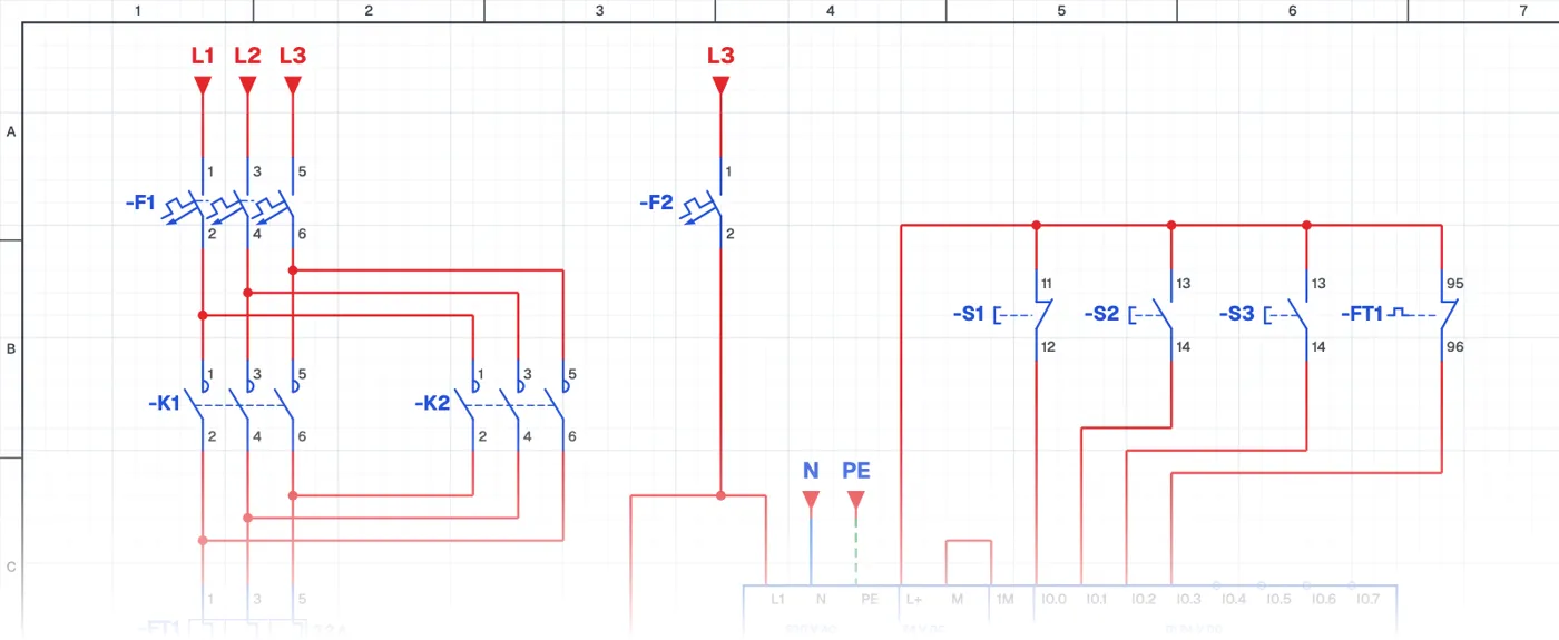
What is interlocked forward-reverse with a PLC?
It is a circuit in which a three-phase motor runs in both directions using a PLC. The two contactors are connected to two PLC outputs. The interlock that stops both contactors from energizing at once is built both in the program and in the wiring.
Where is it used?
It is used in PLC-controlled cranes, doors, conveyors, packaging machines and machine tools. Every automation system that changes direction has this structure.
PLC wiring and ladder program
The power circuit is the same as the classic forward-reverse circuit. The interlock in the program stops both outputs from switching on together. The interlock in the wiring uses the contactors' normally closed contacts and prevents a short circuit even if the program is wrong, a PLC output sticks or a contactor jams mechanically.
Why two interlocks?
On site, safety is never left to a single layer. The software interlock handles normal operation, the hardware interlock handles faults. This principle applies to every PLC-controlled power circuit.
Parts used
- Motor 3~
- M1
- PLC
- PLC1
- Start button (NO)
- S2, S3
- Contactor coil
- K1, K2
Run it in the simulator.
This circuit is ready in the CoilPath library. Open it, press the buttons and follow the current. It also comes with a wiring view and a panel layout.