Frequency drive (VFD)
What is a frequency drive?
A frequency drive (variable frequency drive, VFD, inverter, AC drive) is an electronic device that sets the speed of an induction motor by changing the frequency of the voltage it supplies. It converts the fixed-frequency mains voltage first into DC, then into AC at the required frequency.
What does a frequency drive do and where is it used?
It starts the motor softly, holds it at the required speed and stops it softly. It is used for energy saving on pumps and fans, speed control on conveyors and belts, and precise control on cranes, lifts, mixers, compressors and machine tools. On pumps and fans, even a small reduction in speed cuts energy use considerably.
Control and speed setting
The drive can be run from its keypad, from buttons wired to its digital inputs or from a PLC. Speed is set from the keypad, a potentiometer on the analog input, a 0-10 V or 4-20 mA signal, or over communication. Acceleration, deceleration, speed limits and control mode are set with parameters.
What to watch out for
Choose a drive suited to the motor's power and current, and enter the nameplate values correctly in the parameters. Use shielded cable between drive and motor and lay signal cables apart from power cables. Choose a suitable RCD type for circuits with drives. A contactor on the drive output must not open while the drive is running.
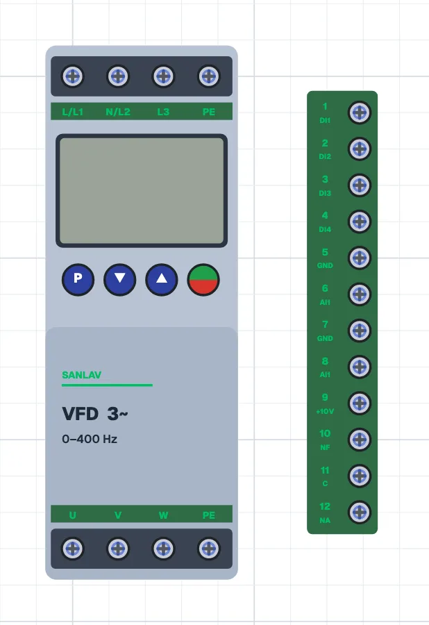
Terminals
Variable frequency drive
- Mains input (L-N single-phase, L1-L2-L3 three-phase)
- Protective conductor
- Motor output
- Digital inputs DI1-DI4 (run, direction, preset speed; chosen by parameter)
- GND
- common of the digital inputs
- AI1
- speed setting input (potentiometer wiper)
- Potentiometer supply
- Relay output
- NF (normally closed), C (common), NA (normally open)
Potentiometer
- End terminals
- supply and GND
- Wiper
- to the analog input
Try it in the simulator.
This component is in CoilPath with its real look. Add it to a circuit, wire it and see how it behaves in the simulation.