Indicator lamp
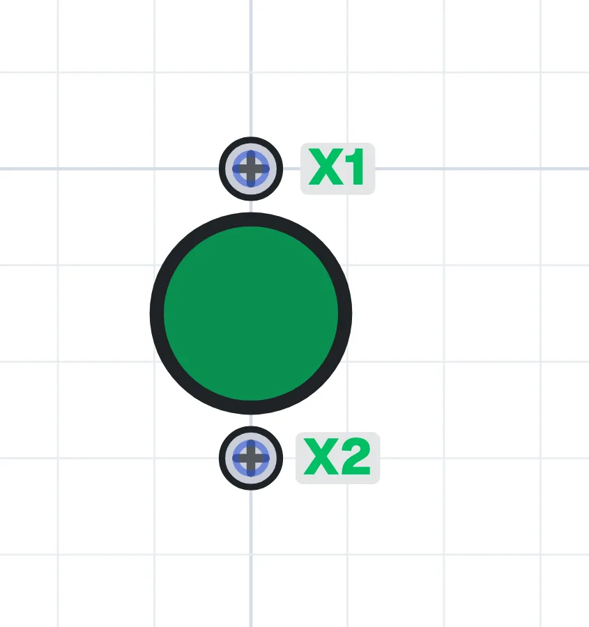
What is an indicator lamp?
An indicator lamp (pilot light) is mounted on the panel door and shows with light that a condition is present. It lights when voltage reaches its terminals. Long-life LED types are used almost everywhere today.
Where is an indicator lamp used?
In motor and pump panels it shows that a motor is running, stopped or faulted; it is also used for power-on lamps, phase lamps, alarms and warnings. It lets the maintenance team see the state without opening the panel.
Colours and their meaning
Colours follow the standards: green usually means running or normal, red means fault or danger, yellow (amber) means warning or that a protective device has tripped, and white and blue are for information. Lamps are made for different voltages such as 24 V, 230 V and 400 V.
What to watch out for
The lamp voltage must match the circuit it is connected to. The meaning of each lamp should be labelled on the panel door. Fault lamps are lit by the signal contact of the device that detects the fault, such as an overload relay or phase monitoring relay.
Terminals
Indicator lamp (green)
- Supply
- X1, X2
Indicator lamp (red)
- Supply
- X1, X2
Indicator lamp (yellow)
- Supply
- X1, X2
Try it in the simulator.
This component is in CoilPath with its real look. Add it to a circuit, wire it and see how it behaves in the simulation.
Circuits that use this component
- Direct-On-Line Starting Circuit with Protection and Indicator Lamps
- Manual and Automatic Pump Control with Signalling, Using a Liquid Level Relay (NO Contact) and Float Switch
- Direct-on-Line Starter with Residual Current Protection
- Start-Stop (Seal-in) with a PLC
- Start-Stop from Three Places with a PLC
- Traffic Light with a PLC
- Box Size Sorting with a PLC
- Start-Stop with HMI
- Product Counting with HMI